Thomas Bunn House Telephone Interaction
| Projects | |

| |
| Project: | Thomas Bunn House Telephone Interaction (I) |
| Description: | |
| Skillset(s) : |
Raspberry Pi • 3D Printing • Python • 3D Modelling • Electronics |
| Project Type(s) : | |
This display is an antique telephone (late 1890s-early part of 20th century) that was provided by the Thomas Bunn House. Their request was to have it play an audio file through the earpiece when the earpiece was lifted and the crank was run.
How we did it
The speaker in the earpiece was in excellent shape. As a result, we were able to build place a Hall sensor, some magnets, and use the existing switches without damaging or removing any of the existing equipment inside the box.
A set of alligator clips is connected to points on the receiver switch to indicate to an RP2040-based microcontroller whether the earpiece was off the hook. When the hand crank is run, a magnet held between the spokes of one of the crank gears moves past a Hall-effect sensor, which creates a small, changing voltage. The microcontroller reads an analog-to-digital converter (ADC) that is connected to the output of the Hall sensor, and, if the value exceeds a threshold enough times, it triggers an MP3 audio board (DFPlayer Mini) to play a random track from the micro-SD card that the user can hear in the earpiece.
Once the audio finishes playing, it goes silent and waits for the next off-hook and crank-detect events. If the earpiece is hung up before the audio finishes playing, the audio is stopped and the device goes idle, waiting for the off-hook/crank-detect events.
A 10Ω, 10W resistor was placed across the crank terminals to shunt any crank energy away from terminals that the user may come into contact with, convert that crank energy to heat, drain any residual charge, and provide some resistance to cranking.
LED indicators in the electronics enclosure will blink status messages in the event that there is a problem; a sheet showing the codes was printed in a similar style to the original schematic sheet and taped over it.
All programming was done using MicroPython.
-
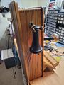 Bunn Phone showing earpiece and receiver
 -
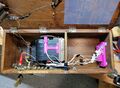 Inside view of cabinet, including electronics enclosure and updated "schematic". Note that original hardware is still in place (and in some cases is used to anchor new components).
 -
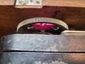 A bright pink 3D printed magnet holder, wired between brass crank spokes
 -
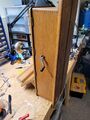 Bunn Phone - view with hand crank


